Fluorescent tubes in general are very efficient in terms of lumens per watt, but their lifetime is very low and this makes them more costly to maintain. LEDs are efficient and have a long lifetime, up to 50,000 hours if they are driven well with appropriate heatsinking.
To make a solution efficient, the idea is to have the isolation between the LEDs and the heatsink instead of using electrical isolation done by a transformer with the PFC flyback topology. It's well known that a flyback topology typically has efficiency of around 80% for low power.
To satisfy the safety requirements a thermal foil will be used between the LEDs and the heatsink which can stand up to 5 kV breakdown voltage, making the system safe for people.
Two solutions are proposed for tube replacement, the first solution is a retrofit which replaces the traditional fluorescent tube with an LED tube and only requires short-circuiting the starter. The second solution is to replace the traditional fluorescent tube and the ballast, and may need an electrician or specialist to install. Since around 3500 lumens need to be generated, 35W worth of power LEDs are necessary, and both solutions will include power factor correction.
The following article will discuss an LED driver concept to meet those requirements. It will explain the implementation of an AC/DC step down converter, driving 30 and 60 high brightness LEDs in one string with very high efficiency and will discuss the problems of the T8 retrofit.
high power LEDs such as Golden Dragon offer high reliability, high luminous efficacy, long lifetime and robustness. Applying these goals during the design procedure of the power supply will provide an LED lamp superior to conventional lamps.
Despite these advantages, there are specific guidelines to follow when designing a retrofit or a non-retrofit lamp. These guidelines are The European standard EN61000-3-2 which sets tight restrictions on Lighting devices with regard to THD (Total Harmonic Distortion) that have power consumption of more than 25W. Additionally those lighting devices need to follow the power factor, safety and isolation requirements.
Since the power is higher than 25W, the LED tube will definitely include an active PFC (Power Factor Correction) to keep the input current in phase with the input voltage.
One of the biggest advantages of a T8 tube is the space available for the heatsink because LEDs need thermal cooling. They convert around 40% of the power consumed into light and the rest is dissipated as heat.
Two design examples will be illustrated and examined; both designs use the Texas Instruments LM3444 controller IC. The first design is a tube replacement which doesn't need to remove the traditional magnetic ballast. The second design is not a retrofit and may need an electrician or specialist to install.
T8 LED tube as retrofit
The architecture is similar to a fluorescent tube, but the tube will include LEDs and electronics. Therefore it's a challenge to put all the electronics inside the tube while still fulfilling all the standards.
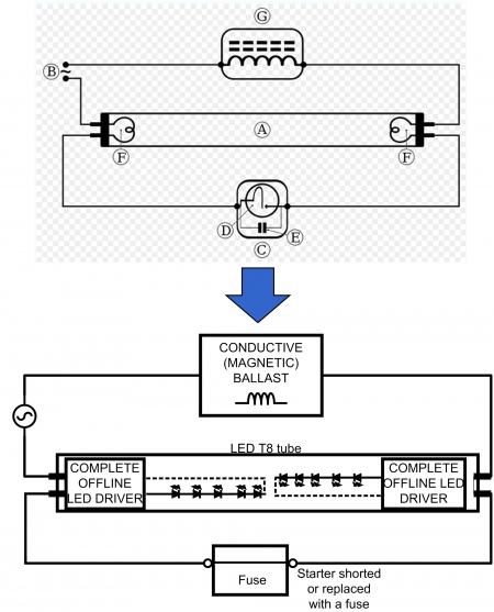
The architecture is shown in figure 1.The starter is simply replaced by a short circuit which will be provided with the tube. As is shown, two power supplies will be used to deliver the power to the LEDs. This structure has the advantage of having the ends of the tube unlit, which is similar to a fluorescent tube. Using only one side will make the tube appear damaged when around 200mm at only one end does not light up.
Our solution will focus on a two isolated PFC flybacks, but it's possible to use a non-isolated buck topology with the LM3444. The non isolated version is detailed in the non-retrofit T8 LED tube. Each driver will provide approximately 15W while driving 12 LEDs in series, which gives an LED voltage of around 45V at 0.35A.
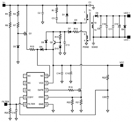
Figure 2 shows a schematic which can be used with the T8 tube with an efficiency higher than 85% and with AC line injection circuitry that enables PFC values of greater than 0.98, this solution fits perfectly inside the tube. The heart of this power supply is the LM3444 which is an adaptive constant off-time AC/DC buck (step-down) constant current controller that provides a constant current for illuminating high power LEDs. The high frequency capable architecture allows the use of small external passive components.
High power factor correction analysis:
A small portion of the line voltage is injected into pin 5 of the LM3444 to turn it into a constant power flyback. By injecting the 1.0VPk rectified AC voltage into the FILTER pin, the main power FET on time, Ton, can be made to be constant in DCM mode, therefore obtaining a good power factor. The design is described in detail in application note AN-2097 from Texas Instruments.
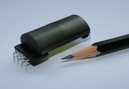
All components will fit into the tube except the transformer, due to its mechanical construction. To make it feasible to fit the transformer inside, the construction needs to be horizontal. Wurth has designed a bobbin and core especially for T8 Tubes that guarantees 6.4mm of Creepage, meeting the requirements for IEC60950 reinforced insulation. The typical core material is a high saturation type with a saturated flux density of 4300 gauss at 100 degree C that can handle up to 20W. This transformer is shown in figure 3.
After the size of the transformer, the component to focus on for size concerns is the bulk capacitor.This electrolytic capacitor has high capacitance to filter the 100 Hz ripple but a limited lifetime which is dependent on temperature and ripple current. Power design engineers should apply a derating of both temperature and ripple current on the electrolytic capacitor to be able to guarantee a certain lifetime.
Non retrofit T8 LED tube
The proposed architecture has the AC-DC driver not inside the tube but external, which is a huge advantage because it provides lots of space for the drive electronics. This solution cannot be simply dropped in the old tube socket. The user must do some re-wiring, and may need an electrician.
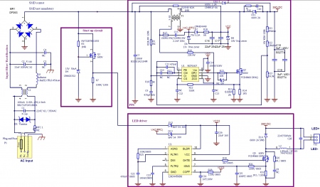
Figure 4 shows the block diagram, and no galvanic isolation is required on the power side so as not to decrease the efficiency. Total system efficiency depends more upon the AC-DC isolating transformer. The PFC flyback is economical but rarely exceeds 85% efficiency.
The isolation is located between the heatsink and the LEDs by a thermal foil or a ceramic isolation. As the isolation is not done in the transformer the efficiency becomes better. The foil which is used between the LEDs and the aluminum heatsink is from Kunze. Its high thermal conductivity offers a low thermal resistance and very strong double sided adhesive that makes it the best thermally conductive foil to use for fast extraction of the heat generated by the LEDs. The isolation consists of using this foil, KU-SAS20, which can stand up to 6.5kV and meets the safety requirements. Alternatively, a second approach is possible by using ceramics heatsinks because ceramic is electrically insulating but has a good thermal conductivity and provides metallisation pads for soldering the LEDs.
A basic AC-DC power supply generates harmonic distortion into the input line and has a poor power factor, therefore is an obstacle to meet the European standard EN-61000-3-2. The proposed solution uses a PFC circuit to make the input current waveform follow the waveform of the input voltage.
For our ballast, the applicable standard to follow is the European standard EN-61000-3-2 Class C.
The PFC works in Critical Conduction Mode and acts as a boost converter. It provides a relatively stable output voltage (380Vdc), that will be the input voltage for the LED driver. The LED driver works as a step down converter with constant current control, which makes the LED driver suitable for use with the rectified input voltage.
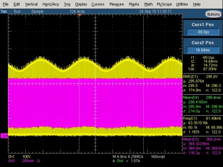
As the LED driver can reject high input ripple, a low value capacitor will be used on the 380Vdc bus voltage. To keep long lifetime, no electrolytic capacitors are allowed due to their failure rate.This ballast uses film capacitors from EPCOS instead of electrolytic capacitors; Figure 5 shows a plot of the 100 Hz ripple voltage at the drain of Q5 of the LED Driver. The envelope of the drain voltage is the output voltage of the PFC seen on the polymer capacitor C 17and C18, the LM3444 filters this 100 Hz ripple by providing constant current into the LEDs.
Figure 5:
CH1: Drain voltage with 100 Hz envelope
CH3: LED current without 100hz ripple
A de-rating has been defined for all components following internal guidelines. This minimises the failure rate and increases the lifetime of the complete system. The LED tube and ballast are already designed and optimised for driving 30 white high brightness LEDs in series at 350mA current with a maximum power capability of 35W. The ballast is protected against the open-circuit of the LED string, short circuit across the LEDs or overload at the output. It has been ensured that no component will overheat and burn in case of a safety issue; this makes the design very robust.
The link to the complete report Rev. E is:
http://www.ti.com/lit/an/snva462e/snva462e.pdf
The main features of the ballast are listed here below:
Input voltage of 230Vac, but this can be extended to a wide range from 85 to 265Vac.
Power Factor of 0.98
Output current is regulated to 350mA
Output voltage depending on LED VF is 100Vdc +/- 20% but can be extended to 200Vdc
Main harmonics limited according to EN61000-3-2 Class C
EMI (Conductive) tested according to EN55022
EMI (Radiated) tested according to EN55022
Efficiency is 87%
Safety standards following our internal guideline
Passive cooling method (heatsink)
Temperature range -20°C to +65°C
Long life time by film capacitor from EPCOS
Conclusion
The retrofit solution uses two power supplies which decrease the overall efficiency and uses electrolytic capacitors which have a major impact on the lifetime of the product, but it’s pin to pin compatible with a standard fixture and does not need a specialist or electrician to install. Leaving the magnetic ballast and keeping it as a standard inductor will also affect the efficiency.
The non-retrofit solution requires the replacement of the tube, the ballast, and a re-wiring of the system, but offers a higher efficiency and a long lifetime. Therefore, when looking for efficiency and lifetime, the T8 tube non-retrofit appears to be the solution.


